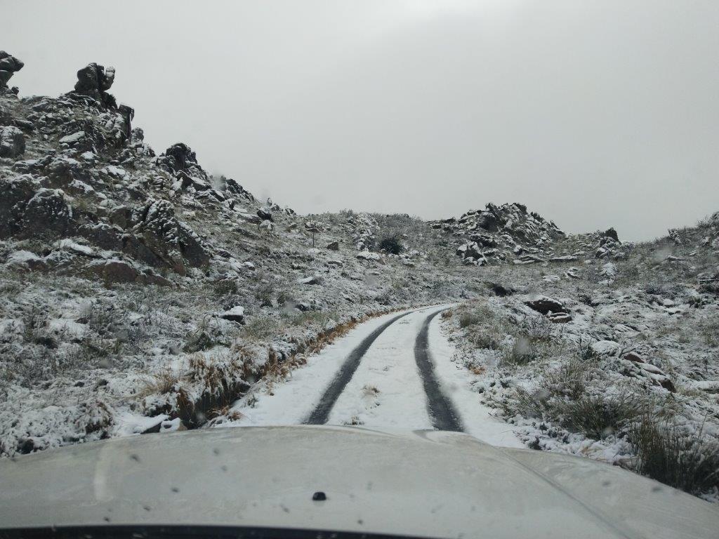
Jan, ZS1VDV and JP, ZS1JPM investigate why the main Eskom power feed was down. This was after snowfall stopped a visit on 11 June 2020.

A breaker was reset after the storm and power was reinstated.

Jan, ZS1VDV and JP, ZS1JPM investigate why the main Eskom power feed was down. This was after snowfall stopped a visit on 11 June 2020.
A breaker was reset after the storm and power was reinstated.
Jan, ZS1VDV and Sybrand, ZS1SJ did some maintenance on the backup power.

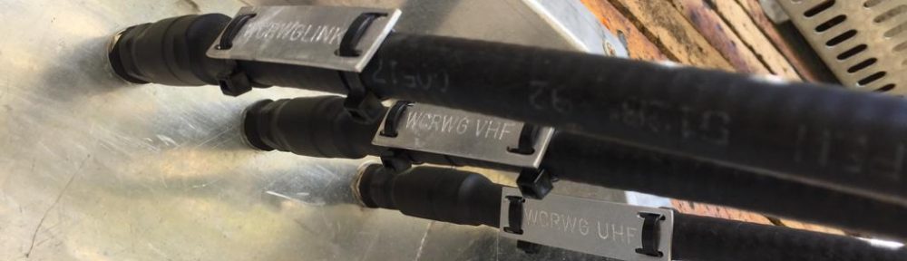
The link controller was reprogrammed and the UHF link repeater SQL was closed a bit.
Jan, ZS1VDV reinstalled the ZU9DBI VHF DSTAR repeaters internet gateway.
Updates was made to the internet link configuration
On Monday 1 June 2020, Jan ZS1VDV and Paul ZS1V visited the Hanskop 145.600 site to assess the damage to the equipment after a burglary that occurred over the weekend prior.
The perpetrators ripped out and made off with the battery charger, multiplug and 220V power lead. Temporary repairs were made and plans put in place to return and complete the restoration.
An investigation was done to get more information for the pause in voice feedback on the UHF link repeater.
Reference voltage was re calibrated for more accurate temperature and battery sensors.
On Saturday 30 May, John ZS1EQ, Paul ZS1V and Jan ZS1VDV visited the Bottelaryberg highsite that hosts the 145.575 DSTAR and 438.300 multimode digital repeaters. While both repeaters were operating correctly, the internet link to the site had been down for several months, limitting the utility of these repeaters.
The internet link was re-established and a general health check of the site was performed. The gateway unit for the VHF DSTAR repeater was found to be faulty and removed from the site. As a consequence the UHF multimode repeater is now fully functional, but the DSTAR repeater is not linked to the internet.
A battery switch over and low voltage cutout unit on the backup batteries was installed.
Jan, ZS1VDV znd Ralf, ZS1RK visited Jonaskop toe investigate why the link controller was down.

It was found that a power plug was intermittent and repaired.
The reference voltage for the temperature and battery sensors was re calibrated.

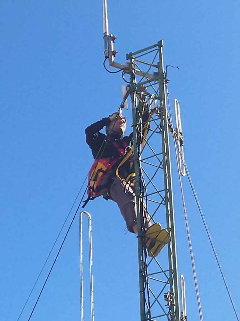
On Saturday 9 May, Jan ZS1VDV and Ralf ZS1RK visitted the Jonaskop 145.675 repeater site. High wind conditions prevented close up inspection of the antenna connections on the tower, but the SWR of all the antennas were checked and found to be good.

The VHF repeater squelch was adjusted. The audio levels were re-aligned and one coax connector was seated correctly.
On Saturday 25 April, ZS1VDV, ZS1V and ZS1RK visited the Hawequa site, home of the 145.650 repeater and 438.800 link repeater between Piketberg and CPUT. The 4 x 200AH backup batteries donated for the purpose were installed with their fusebox and charger.
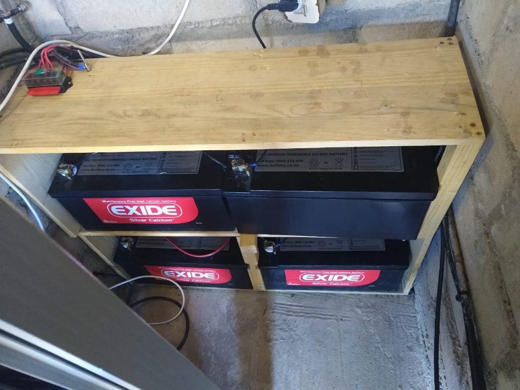
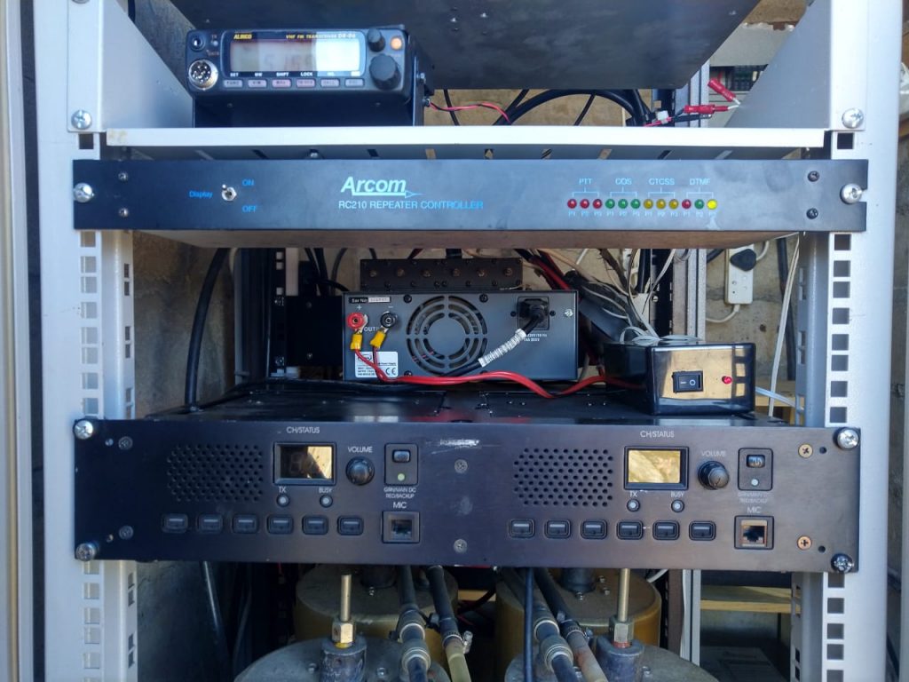
In addition the Vertex/Motorola repeater system swapped out for a pair of Kenwoods, a TKR750 VHF and a TKR850 UHF.
The waterproofing of the antenna connectors was also inspected and found to be in good order for the coming winter.
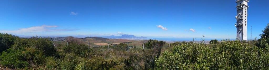
Meetup at gate (at tar road) +_ 09:00.
Drove up.
VHF Repeater
Connected a test repeater direct to duplexer (By passed all filters and pre amp except duplexer). Repeater was set at 0.22uV to open.
Received ZS1GVW with lots of rain on signal (ZS1GVW running 20w)
Received ZS1GVW clear (ZS1GVW running 60w)
Did receive some interference on RX.
Tested if CTCSS was a good enough filter (Confirmed).
Local RF noise suspected to be around 0.3uV
Removed 1 can from Celwave cavity set and retuned for 145.750 (-0.58dB insertion loss)
Replaced VHF Engineering Bandpass filter with Celwave cavity (Insertion loss moved from -2.7dB to -.58 dB)
Bypassed one of the two cavity bandpass filters in RX side (left -0.97dB)
Reconnected the installed PYE repeater.
Power after duplexer up by 60% +_ 15W output now.
UHF repeater:
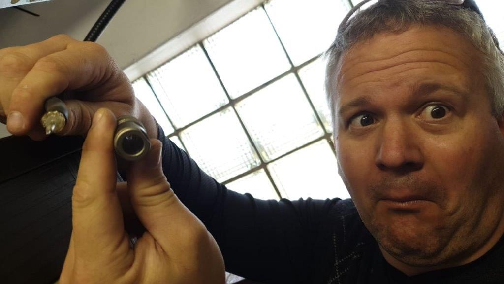
Checked all cables.
Fixed N-male connector on RG214 between duplexer and repeater in RX path)
Retuned duplexer (434.625 -0.79 dB / 433.025 -1.38 dB / 102 dB isolation)
Placed duplexer back.
Measured power and SWR:
Repeater output 30W SWR 1
After circulator 27W SWR 1
After duplexer 22W SWR 1 (With dummy load)
After duplexer 22W SWR 1.4 (With antenna)
Tested sensitivity direct on repeater (3.5uV)
Investigated repeater. In process of investigation sensitivity went down to 0.55uV, but lots of rain) Could not measure 12db sinad, but suspect it to be around 5uV (the by ear test).
Sensitivity was at 0.55uV at end.
Finshed around 14:30 and drove down.
Summary
More thinking will need to be done about Heliax state.
VHF Repeater
TX side: improved output by swapping out band pass filters (2.1 dB improvement, output now 15W)
RX side: removed 2 cavity bandpass filters (improved RX by 3.63 dB)
UHF Repeater
TX side: improved by 0.83 dB
RX side: improved by 4.7 dB
UHF repeater is not healthy.
TODO:
Investigate Antenna options VHF
Investigate why 1.4 SWR on UHF
Decide on Feeder
Think about linking
Service UHF Repeater