Jan ZS1VDV reprogrammed the Allstar link radio to the Hawequa UHF repeaters frequencies 438.800 Mhz.
Jan ZS1VDV reprogrammed the Allstar link radio to the Hawequa UHF repeaters frequencies 438.800 Mhz.
Paul ZS1V and Jan ZS1VDV did some maintenance on site. This was the 3rd attempt to go to site. The previous attempts failed due to a GSM failure on site preventing de-arming of the alarm. Last night a remote was used to de-arm the alarm. For a few while the alarm did scream inside the hut (an unpleasant experience that is not recommended).
Left for site: 16:30
The WiFi based site internet link device firmware was updated and the link reconfigured. The Multimode Digital UHF repeater and VHF DSTAR repeaters are back consequently back online.
Some power maintenance was done and monitoring equipment installed.
The Allstar link node was installed. It is currently running on 433.500 MHz simplex. This node is linked to the WCRWG hub node, which has a permanently linked node to the Gifberg 145.7375 repeater. Once testing is complete, the link node radio will be switched to link to the Hawequa 438.800 UHF repeater, bringing Gifberg onto the main link network.
Some general network maintenance was completed.
The weather on site was foul and the wind made the walk out with equipment in the dark treacherous.
Home and unpacked 20:30.
It was a challenge to predict the correct maintenance slot for Jonaskop. The weather changed a few times in the week.
David ZS1DDK picked up batteries, which was fetched from him during the week by Jan ZS1VDV. Rassie ZS1YT facilitated all payments.
John ZS1EQ delivered the automatic switchover and LVD (Low Voltage Disconnect) / OVD (Over Voltage Disconnect) box to Matt ZS1MTF on Friday evening.
A team consisting of Matt ZS1MTF, Nic, James ZS1RBT, Paul ZS1V and Jan ZS1VDV went to Jonaskop to upgrade the emergency battery capacity, install the automatic switchover and LVD/OVD box, replace all cable ties (lasted about 8 years in the sun) and tension the tower stays.
Saturday morning started at 06:00 packing the vehicles.
Left home around 06:30.
08:30 stopped at site. The weather was not cold with a moderate breeze, which turned into a strong breeze as the day progressed.
11:30 done and left site.
13:00 safe home.
Jan ZS1VDV and JP ZS1JPM, serviced Hawequa charger circuit.
Left Stellenbosch 17:15
On Site 18:15
Found a fuse holder failure.
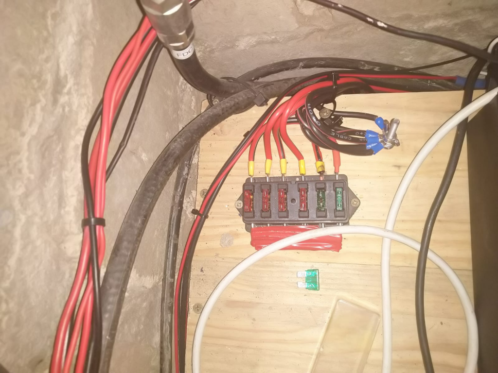
Removed failed fuse
Replaced wire between fuse box and charger
Left site 19:30
Home 20:30
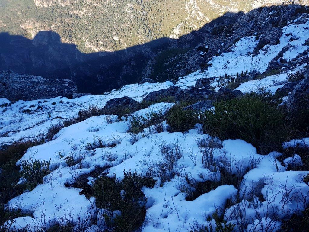
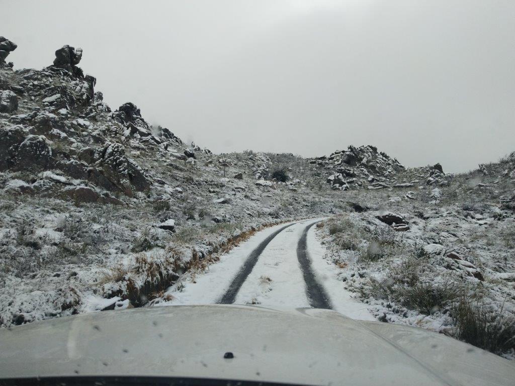
Matt ZS1MTF, JP ZS1JPM and Jan ZS1VDV investigated the power outage at Jonaskop. The sun was out, some wind was blowing and some left over snow was visible.
An upstream Eskom breaker was reset.
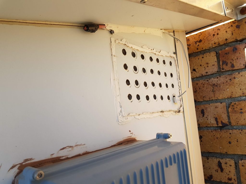
With the storms, the hut took a bit of a beating. The one air vent cover needed to be replaced and the outside temperature sensor wire repaired.
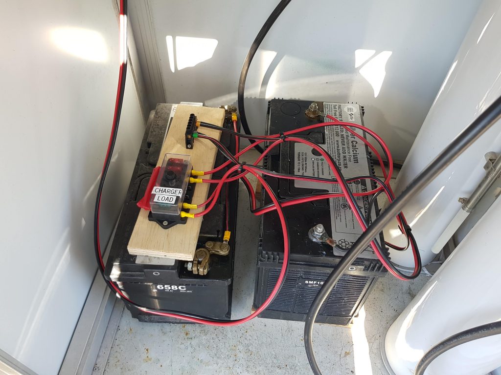
The backup battery distribution was upgrade and fuses installed. The site is now ready to take an easy install of 2 more batteries.
Matt ZS1MTF and Jan ZS1VDV investigated the UHF repeater on Hanskop.
It was found to be in working order. The SQL level of the UHF repeater was measured at 0.43uV.
Michael ZS1TAF did a quick on site diagnosis on 26 June 2020 and found that the controller needed reconfiguration.
Paul ZS1V and Jan ZS1VDV went to Piketberg on 27 June 2020.
The controller was reinitialized, firmware reloaded and reconfigured. (Last done 3 November 2018)
The VHF antenna system was found to have a 2+ SWR, and needs servicing.
Jan, ZS1VDV and JP, ZS1JPM investigate why the main Eskom power feed was down. This was after snowfall stopped a visit on 11 June 2020.

A breaker was reset after the storm and power was reinstated.

Jan, ZS1VDV and Sybrand, ZS1SJ did some maintenance on the backup power.

The link controller was reprogrammed and the UHF link repeater SQL was closed a bit.
Jan, ZS1VDV reinstalled the ZU9DBI VHF DSTAR repeaters internet gateway.
Updates was made to the internet link configuration