Kanonkop maintenance 20191019

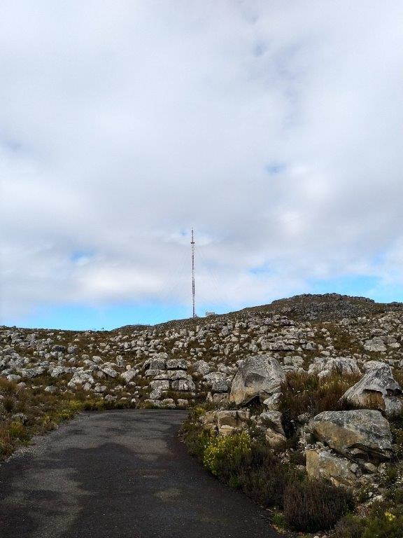
Meetup at gate (at tar road) +_ 09:00.
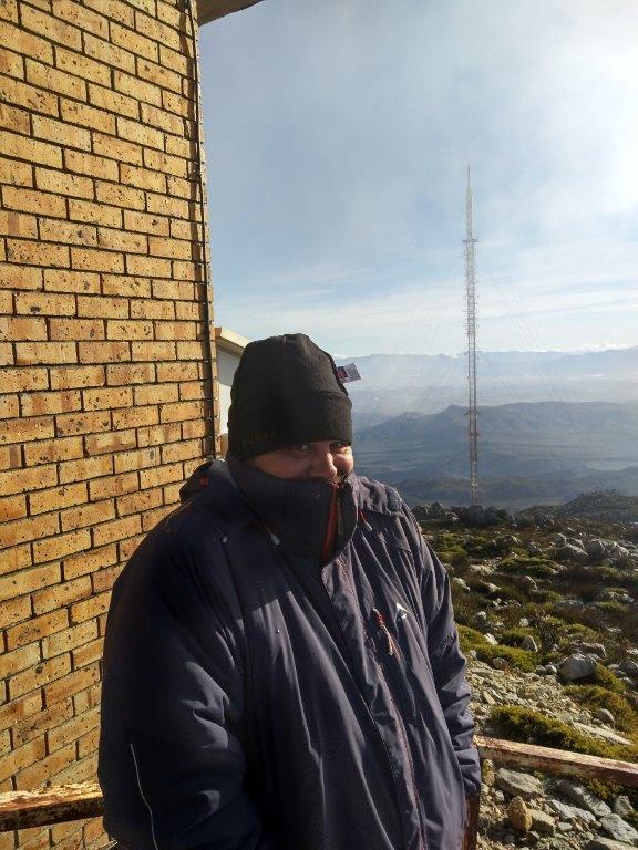
Drove up.

VHF and UHF stacks below dish on right pointing toward left of Robben Island

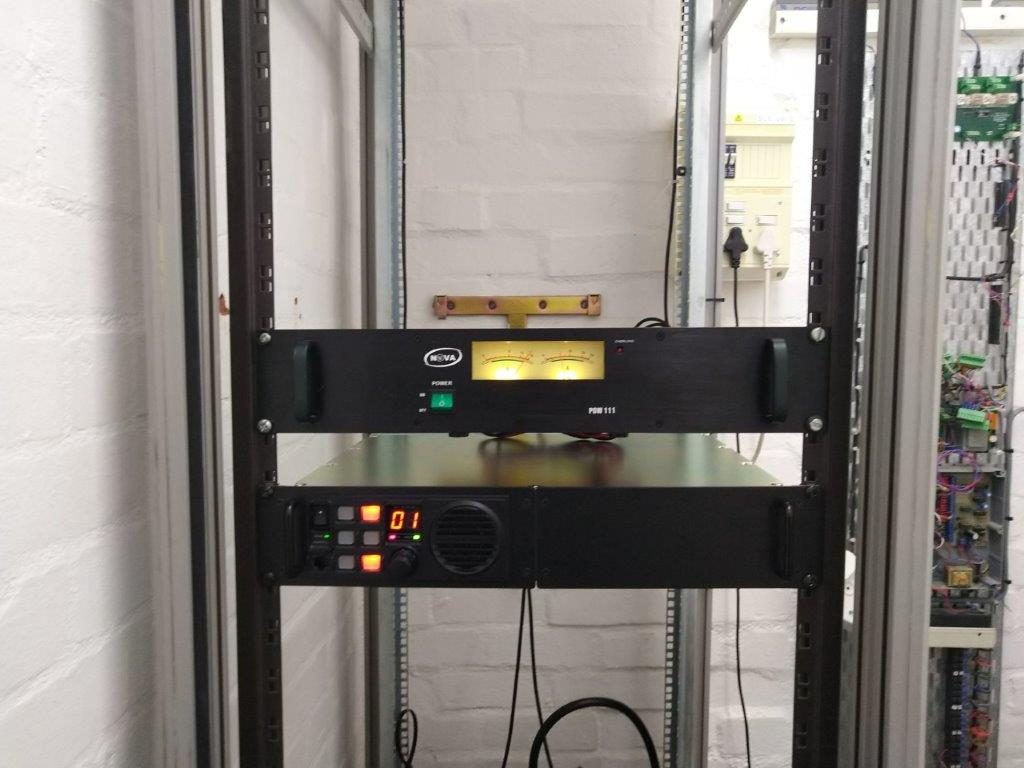
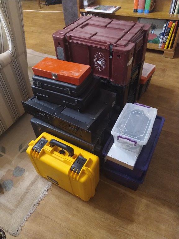
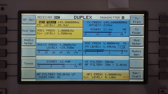
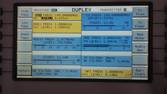
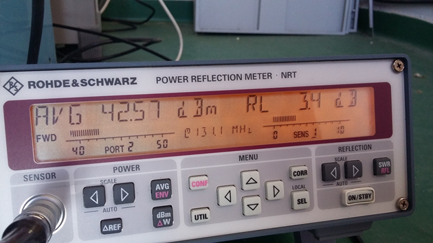
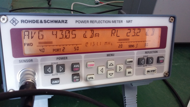
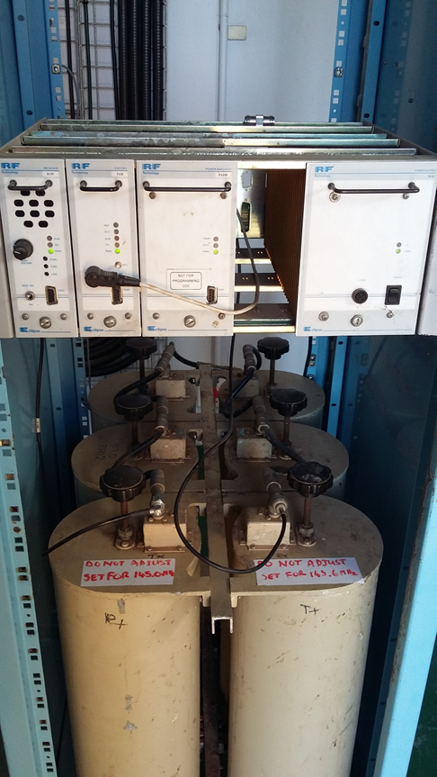
Measured Power and SWRs

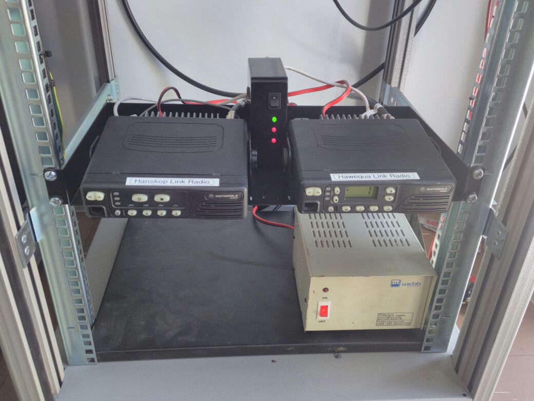
Batteries 13.3V and 13.2V
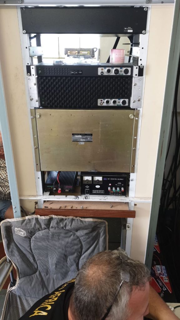
Power Supply Unit right 26.64V
Power Supply left (DC to DC) 13.7V
Power Supply RHS against rack (DC to DC) 13.8V (Negative grounded on rack)

Between Duplexer and Heliax 10W SWR 1.4
Between T4002 and circulator 30W SWR 2
Between Circulator and Band Reject Filter 16W SWR 1.7
Between Band Reject Filer and Duplexer 13W SWR 1.4

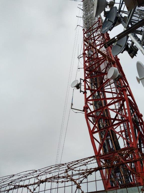
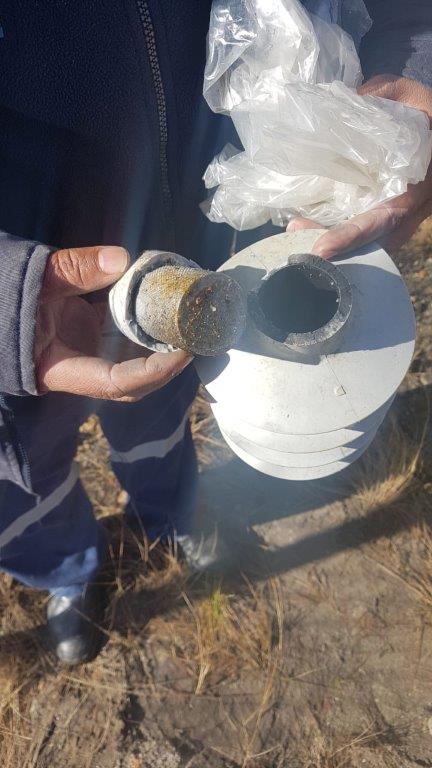
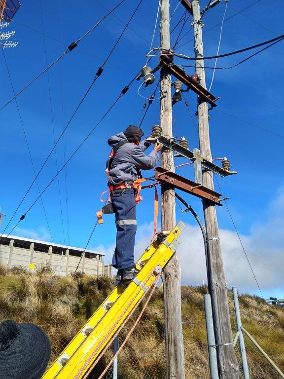
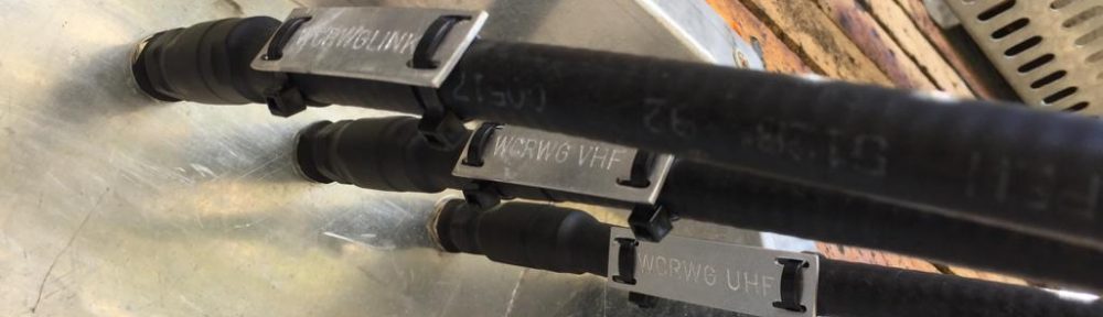
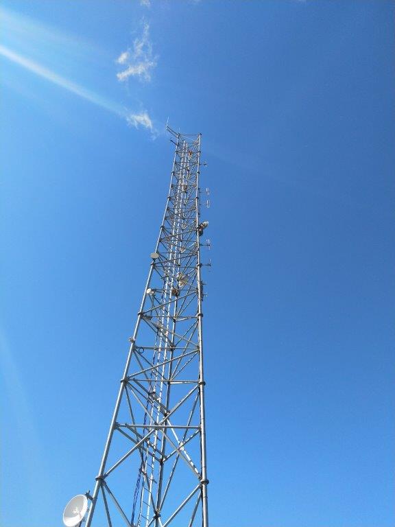
Tested Heliax and Antenna

Used hand radio as source
Bottom 6W SWR 1.4
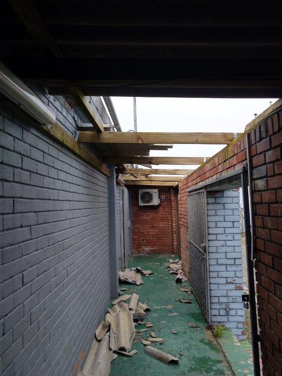
Removed antenna and replaced with dummyload
Bottom 6W SWR 1.4
Top 5W SWR 1
Reconnected antenna
Top 5W SWR 1

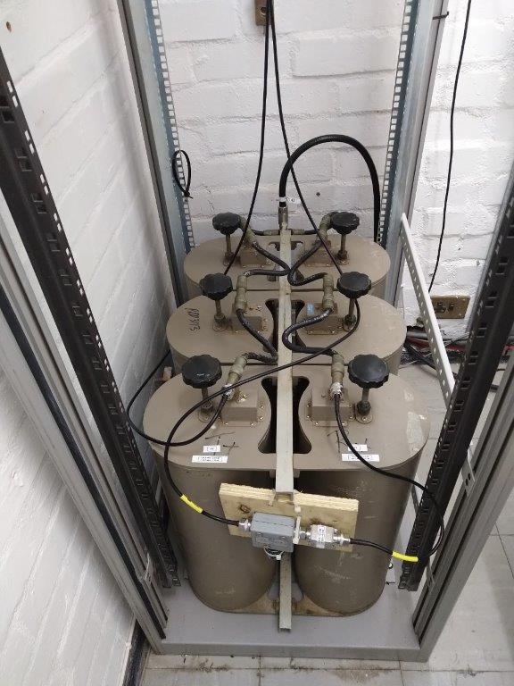
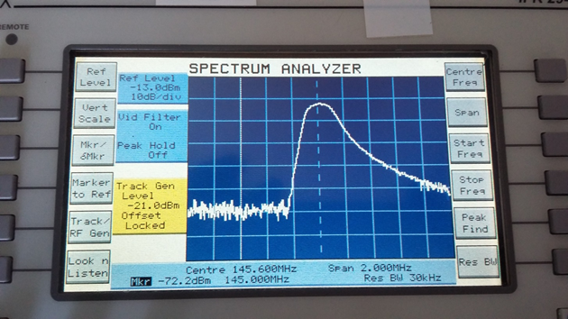
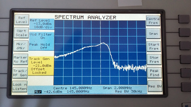
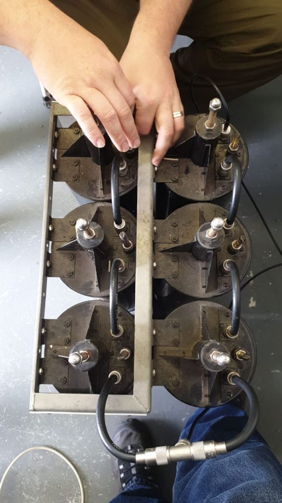
The 2 stage circulator was retuned to correct SWR problem (145.750 before -1.2dB SWR 2 after tuning -0.38 dB SWR 1) The first cap in circulator is suspect.
Bandreject (Notch) filter on 146.2375 was measured and the one nut was tightend
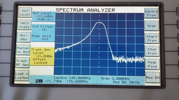
The duplexer was measured and retuned to get a beter insertion loss on 145.150 (before -1.95db after -0.74db) (One cable in harness was found to be wrong length and was replaced)
Wideband bandpass filter was measured. This was connected between cavity bandpass filter and preamp. Moved to be between circulator and bandreject filter.
Cavity bandpass filter was retuned for beter pass band. (before -5.71dB after -4.6dB)
Tested gasfet preamp (145.150 +16 dB)

Tuning VHF Duplexer

All equipment was labeled with measurements.

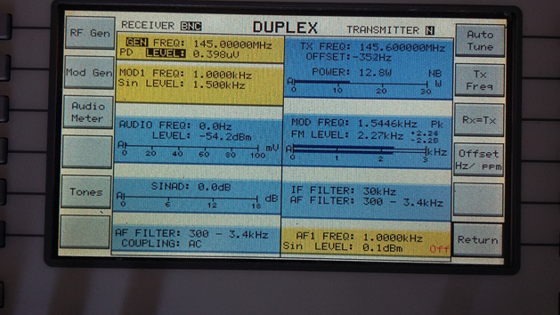
Repeater sensitivity measured -0.4uV

Everything reinstalled and some final measurements

Between T4002 and circulator 30W SWR 1
Between ciculator and Wideband bandpass 27W SWR 1
Between wideband bandpass and band Reject filter 12W SWR 1
Between band reject filter and duplexer 11W SWR 1
After duplexer, just under 10W
Sensitivity after duplexer 0.3uV

VHF Repeater and UHF Repeater

Tested UHF dipole antenna on side of building (good strong signal to 438.800)

Cleaned up and drove down +_ 15:30.

Summary
More thinking will need to be done about Heliax state.
TX side: losses was improved and corrected, but with the introducing of the wideband bandpass in the correct place, no power was gained.
RX side: removed wideband bandpass (2.2 dB improvement), returned cavity bandpass (1.1 dB improvement), retuned duplexer (1.2 dB improvement) Total 4.5 dB improvement

TODO:
Investigate Antenna options
Decide on Feeder
Think about linking
Retuned Wideband bandpass Filter to have less loss on 145.750 (currently -2.7db)
Move preamp before cavity BP filter. (This would just make more sense to amplify, before filter)
Remove one can from Cavity BP filter, retuned for 145.750 and replace wideband BP filter. (Will make about 1.2db more sensitive on RX and about 2dB less loss on TX)
Service UHF

Constantiaberg maintenance 20190831

On 23/24 July the Motorola repeater was damaged in a storm. It is suspected that the repeater was damaged by static from lightning.

Roof damaged by storms

On 26 July Jan ZS1VDV and Paul ZS1V investigated and found the repeater damaged. The repeater and duplexer was removed. The antenna SWR (1:1.03) was checked.

In the following weeks a new install was planned:

  • a backup repeater serviced by Verstay (ZS1VDV, ZS1V)
  • correct length coax acquired (ZS1VDV, ZS1YT)
  • duplexer tuned (ZS1VDV, ZS1V)
  • circulator tuned (ZS1VDV)
  • power supply connector replaced (ZS1V)

The morning of 31 August started at 06:00 with the last few tests of the configuration. Backed all equipment and tools. Left for site around 07:30

Repacked all into 4×4 vehicle at ZS1DDK.

View of Hout bay

On site around 10:00

Duplexer and circulator

Installed duplexer (Decibel Products 6 can). It was tuned to -2.04 dB insertion loss on RX, -2.5 dB insertion loss on TX, and -115 dB isolation between RX and TX). Next was the installation of the rack mount power supply (13.82 V) and Vertex VXR 9000 (sensitivity set to 0.25 uV) repeater.

Power Supply and Repeater

SWR was rechecked between repeater and circulator, circulator and duplexer as well as after duplexer, all was found to be perfect flat (1:1.05). The power output after the duplexer is 14W.

Folded Dipole just above first landing

A few test contacts was made to confirm all working.

Packed all equipment and boxes and returned home at around 11:30

A quick lunch sponsored by ZS1DDK was enjoyed at Peddlers on the Bend.

Hanskop maintenance 20190707

Problem: About 2 months after the big rebuild in September 2018, the UHF repeater was starting to drop out after a few seconds of transmission.

This lead to a long fault finding process with help from the high site managers’ personnel to save on trips to site, on a very bad road.

After 4 months of problem finding, it was concluded that was not the repeater and not the antenna, but most probably the duplexer.

The WCRWG do not have a spare 1.6MHz split UHF duplexer. One was constructed out of spare notch cans. This happened over a process of 2 months, to make up a custom duplexer coax harness and trying to get the pass-through SWR as low as possible. With everything ready, it took some planning to get the vehicle, weather and correct people aligned to go do the swop out repair on site.

It started at around 06:30 today. Packed the repeater, swop-out duplexer and all required tools. Next was the pickup of keys.

Vehicle packed and ready, All in good spirit after the coffee ZS1V provided

The team (Sybrand ZS1SJ, Paul ZS1V and Jan ZS1VDV) got together at around 08:00 to repack all equipment into the 4×4 to go up.

Hanskop in the clouds

Around 08:15 the trip up started. Sybrand got a few chances to use the 4×4 capabilities of his vehicle.

On site the repeater was reinstalled. Next the debugging of the high SWR around the duplexer was completed. SWR straight on antenna 1.2. SWR through duplexer to antenna 1.8. SWR through duplexer to dummyload 1.0. It was concluded that the current duplexer on site was also not the problem. With a bit of head scratching a short patch lead was added to the antenna feedline. That took the SWR through the duplexer down from 1.8 to 1.3.

The last part was to correct the power sensing of the controller. Suddenly the UHF repeater started to restart on transmission. With some debugging it was found that the 10 A PSU used on the UHF repeater was suspect. This PSU was removed and the UHF repeater moved over to the main 30 A. The total current draw is just below 20A on full transmit. The calibration of the power sensing was updated and the voice responses also updated.

DTMF:

  • 8323 – Controller Voltage (This is the main power supply when on mains, and battery when on backup power)
  • 8324 – Main PSU voltage
  • 8325 – Battery voltage
Team photo in the clouds with tower in the back

Everything was packed up and returned home. Home around 13:00 and unpacked by 13:30.

Jonaskop maintenance 2019-06-29

On 26 June it was reported that the repeater is not functioning and constant keying.

From the detailed fault report it was concluded that a power supply is the most likely problem. However with power problems, there could also have been big equipment failure.

Paul ZS1V and Peter ZS1PDE assisted with the ordering and pickup of a replacement PSU for the site.

Jan ZS1VDV packed for all scenarios on Friday evening. This included making controller link cables for the spare repeater.

All equipment ready and packed

Saturday started very early with Sybrand ZS1SJ meeting up with Paul to collect keys and replacement PSU in Somerset West.

Sybrand next was picked up Jan ZS1VDV and loading all equipment in Stellenbosch at around 07:20.

Sybrand driving 330km for the day

A route via Worcester to Jonaskop the best option, as the Franschhoek pass was closed and the round via Grabouw to Villiersdorp was reported on Thursday to have loads of sand after the winter storms,

Arrived on site, it was very clear that this was going to be a very cold and windy visit. Around -2.5 C and very strong gusts of wind.

Sybrand hiding from wind

As soon as the repeater hut was opened, it was found that the repeater was on backup power (measured to be 12.8V). This was very strange as the repeater never went to backup power during the week. Next the PSU and 220V was tested all over the site, and found the no 220V was available. With out more information, it was decided to swop the PSU.

Isolator after lighting strike

On the way down, Eskom was found working on the line. At this stage it was clear why the repeater was on backup power. In the process of driving up, Eskom switched of the 11 KV line to work on it. The 11KV line was hit by lightning and an isolator needed to be replaced. With the one line on the delta 11 KV line down, the transformer would have converted to 220V star 3 phase, but the 220V would not have been stable. After about 1.5 hours the repair was concluded. They had to use a gas flame to shrink the heat shrink on the lug.

Eskom replacing isolator

Returned to site, checked that all power was up and running. It was found the that controller configuration was corrupted and needed to be updated. The main and battery sense DTMF codes was also swopped as listed on the TODO list for the site.

Jan using repeater hut door to hide from wind to configure controller

The link radio the Hanskop audio levels could not be realigned as it was just to cold and wind to strong.

The tower guy lines was giving a quick inspection and found that they will need service on next visit.

Unpacked in Stellenbosch around 14:00.

Sybrand last stop at home around 14:30 for a total round trip of 330km.

Sutherland Repeater maintenance 2019-06-11

Transmitter:

Output power:                  21.6W
Frequency error:              -315Hz
Deviation:                          1.49kHz

Receiver:

Sensitivity:                          0.683uV for 12.2dB SINAD (NOT CCITT weighted)
                                             @1.5 kHz deviation AT 1kHz
Squelch                              Could not be measured. Comms test set only goes down to 0.350uV

TX Filter unit:

RF power before filter:   42.63dBm (18.3W)
Return loss:                       3.4dB  !!!!!!(VSWR 1:5.23)
RF Power after filter:      34.3dBm (2.7W)
Antenna Return loss:      15.7dB (VSWR 1:1.39)

After tuning the filter unit, I got the following results:

RF power before filter:   42.85dBm (20.1W)
Return loss:                       23.2dB (VSWR 1:15)
RF Power after filter:      40.34dBm (10.3W)
Antenna Return loss:      15.7dB (VSWR 1:1.39)

RX Filter unit:

Measured loss at intended frequency:     20.6dB
Isolation at plus 600kHz                               Around 50dB

After tuning the filter unit, I got the following results:

Measured loss at intended frequency:     2.4dB
Isolation at plus 600kHz                               Around 50dB

Repeater without filters at high input RF level; 20uV 88.5Hz CTCSS @400Hz and 1.5kHz deviation @1kHz tone

Repeater without filters at low RF level; 0.683uV 88.5Hz CTCSS @400Hz and 1.5kHz deviation @1kHz tone

RF power going into the filters. Note poor return loss.

After tuning the filter. Note marker on 145.000MHz. Reference at the -10dB mark.

Results after tuning the TX filters.

Receiver filters before tuning: Reference is at the -10dB mark (-22.6dBm) indicating filter loss at 20dB.and off frequency.

Receiver filter after tuning. 2.4dB loss and on frequency. +600kHz isolation of around 51dBm

Repeater performance through both TX and RX filters after tuning filters.

The Site: Gentle reminder not to tamper……..

Conclusion:
I could probably get better results tuning the filters if I had the directional coupler with me. Maybe next time. I would have also preferred to have the manufacturers specifications to test against but did not have at the time. In my experience the repeater performs well according to what I measured. I tested the repeater from the town using a 5W hand held radio and got full quieting from the repeater with good quality audio. I there is someone who can test from the N1, some feedback would be great.

Report compiled by Neville Gleeson (ZS1NEV)

Site tested by: Neville Gleeson (ZS1NEV) and Deon Lamprecht (ZS1AFU)

Maintenance Hanskop 20180707

Jan (ZS1VDV) and Rassie (ZS1YT) went to Hanskop reconfigured the repeater controller and did all measurements for the big site power upgrade and antenna migration.

Most site visits starts the evening before the time with a 1 hour planning and packing session.

Tools and Spares for trip

Wake up 06:30, pack vehicle.

Leave for Strand 07:30 from Stellenbosch.

Pickup key 07:45.

Drive to site, which was very long and challenging drive. Had to “find” a way to the top.

“Finding” the road

MMMM, where to now?

Some holes with bakkie for size reference

08:45 arrive on site.

With all the power interruptions and no backup power, the site controller’s EPROM got corrupted. Reprogrammed the controller. Changed default for links to VHF and East. (please see updates DTMF updates on Hanskop)

Did some detail measurement for coax and battery placements.

10:00 left site.

11:45 Home in Stellenbosch

12:00 Finished unpacking.

Bottelary Maintenance 20180629

View from top in mist

Mast in mist

ZS1SCI (Ohan) and ZS1VDV (Jan) went to site around 17:00

UHF repeater ZU9DMR running DMR, D-Star and YSF

The reconfigured UHF repeater ZU9DMR was reinstalled on site.

A new gateway was installed for the VHF D-Star repeater.

Last view of site, with alarm activated

The site was left around 18:45.  The drive down in the dark and mist was a big challenge.

Maintenance Piketberg, Hawequa and Bottelary 20180113

Jan (ZS1VDV) and John (ZS1EQ) did a round trip to service 3 sites.

Started to load the bakkie 07:00.

Left Stellenbosch around 08:00 and reached Piketberg by 09:45

At the end of 2017, the Piketberg VHF repeater was removed.  The repeater was serviced by Verstay.  The final transistor was replaced.  A replacement duplexer was prepared during the week. The duplexer was swapped out and VHF repeater reinstalled.  SWR between duplexer and VHF radio was 1.2 and between the duplexer and antenna 1.3.

Left Piketberg 11:15 and was on Hawequa at 12:45.

The 10 amp battery charger was swapped out for a 7 amp battery charger.  The 10 amp is designated to go to Hanskop.

Left Hawequa 13:45 and reached Bottelary at 14:45.

Removed the UHF DMR repeater for service.

Back in Stellenbosch and unpacked by 16:15.

Maintenance Back2Back 20171209

The UHF back2back link was moved from the QTH of ZS1DDK to Libertas on 4 November by ZS1DDK and ZS1TAF.

More maintenance was done today by ZS1VDV and ZS1TAF.

Today the equipment was moved on to racks in the cabinet and a link controller was installed.  A powerpole distribution block was added and all power connections migrated to powerpoles.

Rack with radios and controller

This controller can now be used to link or unlink the back2back via DTMF codes.

8500 = Link

8504 = Unlink

Maintenance Hanskop 20170722

Jan (ZS1VDV) and Rassie (ZS1YT) went to Hanskop to investigate the controller not responding to DTMF.

Started packing vehicle 06:30, left Stellenbosch 07:00.

Had to drive very slowly up as the road is in very bad condition and had the sun just over the horizon.

On site by 08:15. The temperature outside was 1.2 degrees, the wind was cutting through everything.

The problem with the controller was found to be interference on the 145.600 Repeater.  The interference is not from our equipment but most likely from WISP equipment.
The 145.600 repeater’s SQL was closed to 1.1uV (about 4 times more that what it should be).  This only helps about 80% of the time. The interference will need more work/investigation.

All SWR was checked. VHF repeater (1.1), UHF repeater (1.1), Jonaskop link (1.6).

CTCSS was added to the 434.650 repeater.

Home at Stellenbosch by 12:45.