Jan(ZS1VDV) started to pack all the equipment at 05:15 in Stellenbosch.
Picked up some Heliax and antennas at (Paul) ZS1V 06:10 in Somerset West. From there it was a quick hop over to get (Rassie) ZS1YT.
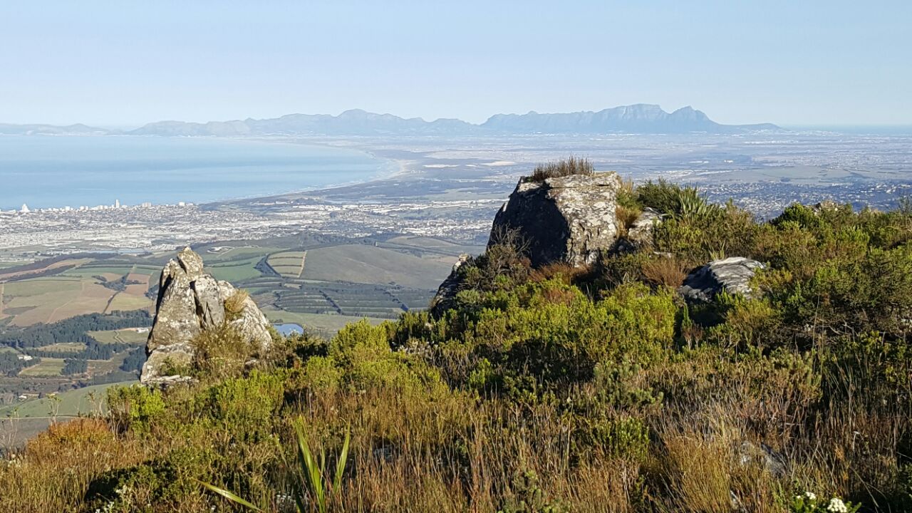
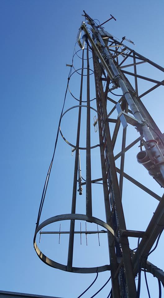
On our way up to the high site, we noticed that we could not see our tower, but did not think much about it, as it could be the angles from the back or maybe weather.
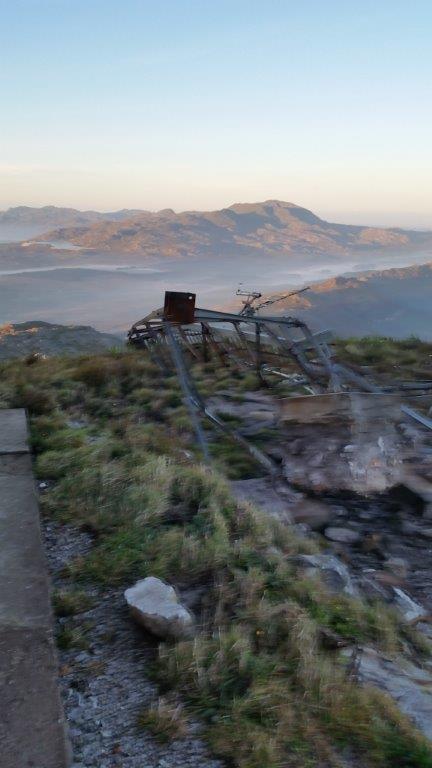
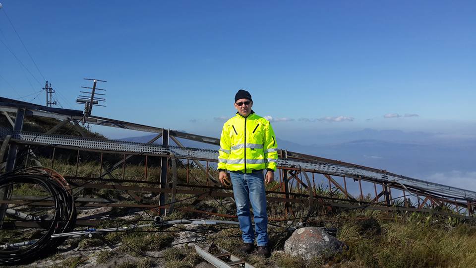
Tower on the ground
When we got on site (07:50), it was very clear that every plan of what was going to happen was 100% out the door. The first action was to recover all our current Heliax and antennas. We lost a RG214 connector (ripped from the cable), the recovered Heliax still needs to be tested but some real bad bends and marks are visible.
Next was to assess if we could do a temporary hack antenna installation with everything on site, which was not possible. With the help of ZS1V the plan was worked out. Andre(ZS1AN) and Kobus(ZS1K) did a few supply store stops and got a pole, more heliax and other sundries from ZS1V to bring to the high site.

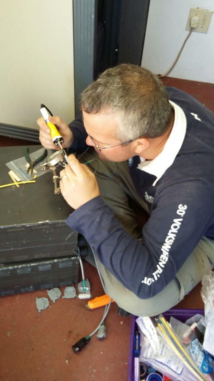
ZS1VDV working on linking cables
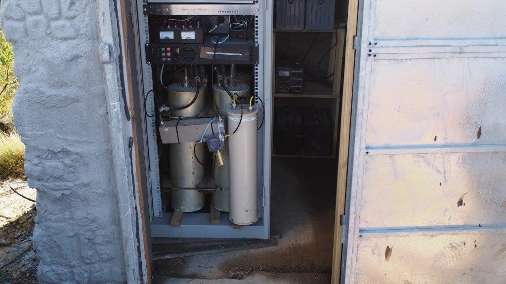
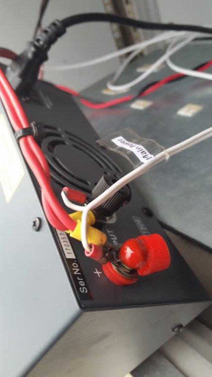
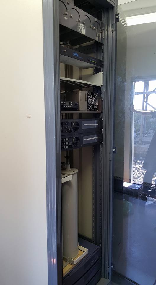
While we where waiting for the supplies, ZS1VDV did a few changes to the controller link cables and audio alignment. A new 20A solid state power supply was installed. The next step was to clean and prep the area for antenna installation.
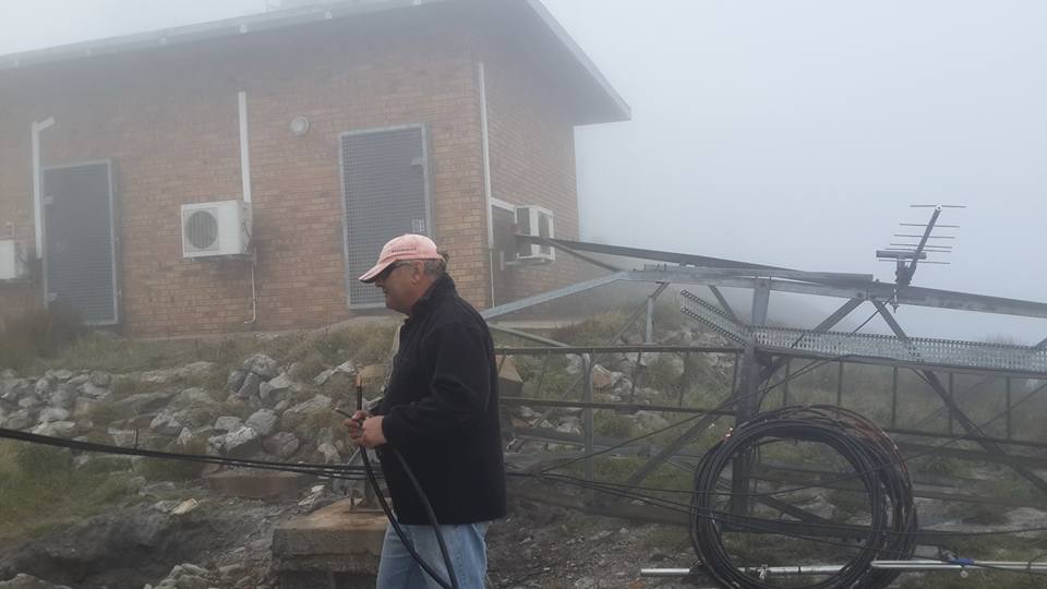
ZS1YT prepping Heliax
ZS1K standing infront of the tower on the ground, which is not very bright 🙂
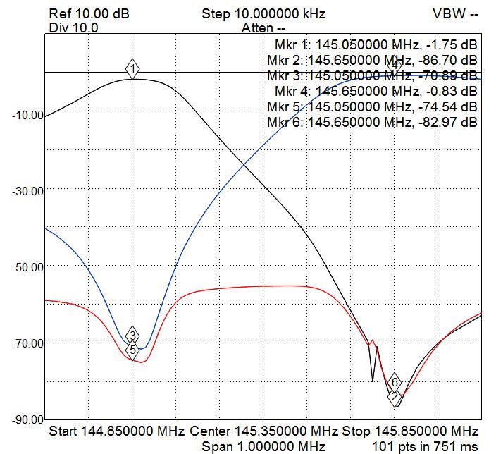
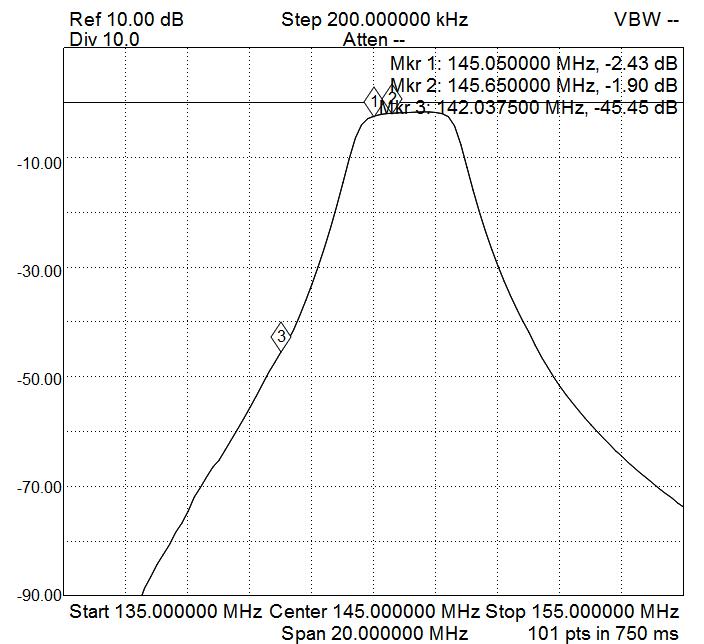
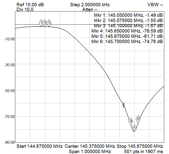
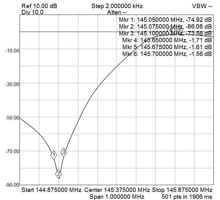
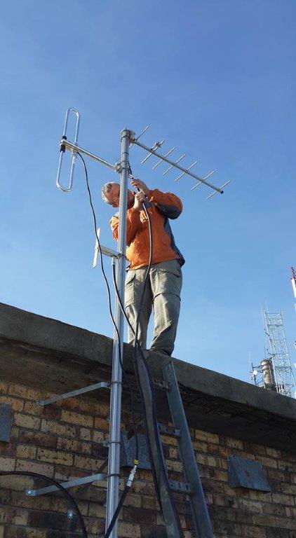
ZS1VDV drove down to the gate to open for ZS1AN and ZS1K. They arrived on site around 13:00. As soon as they arrived the weather started to turn for the worse. ZS1AN and ZS1K installed the 2 mounting brackets and ZS1VDV and ZS1YT prepped the new Heliax to be installed. Then ZS1VDV had to install the antennas on the mast in some very big wind and wet weather. A new FDC145 was installed for the VHF antenna, the dipole was reused for the UHF repeater and another UHF yagi was installed and pointed towards Jonaskop. The SWR was measured. The VHF SWR was 1.7 which was a bit high, but in the weather and time frame could not be corrected. The UHF repeater and link SWRs were 1.5 and 1.4. At this point it was also identified that there is a power problem on site as every now and then when touching a coax, a shock was felt. This was not ignored, just not enough time to resolve it at get everything running again.
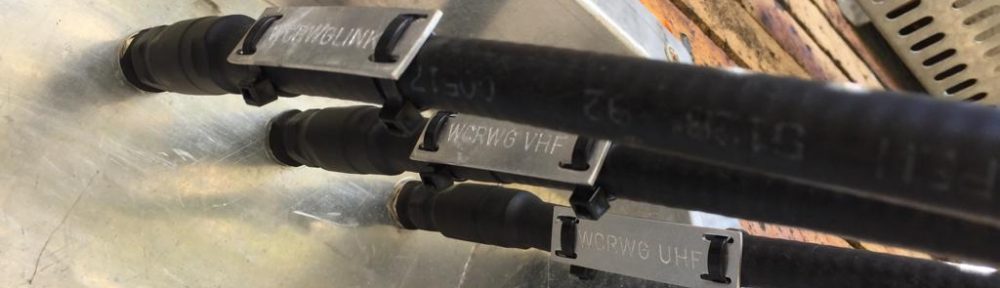
Sealing cables
In a very small weather opening, the connectors was sealed. The last steps was to cable tie all the new Heliax and clean up the site.
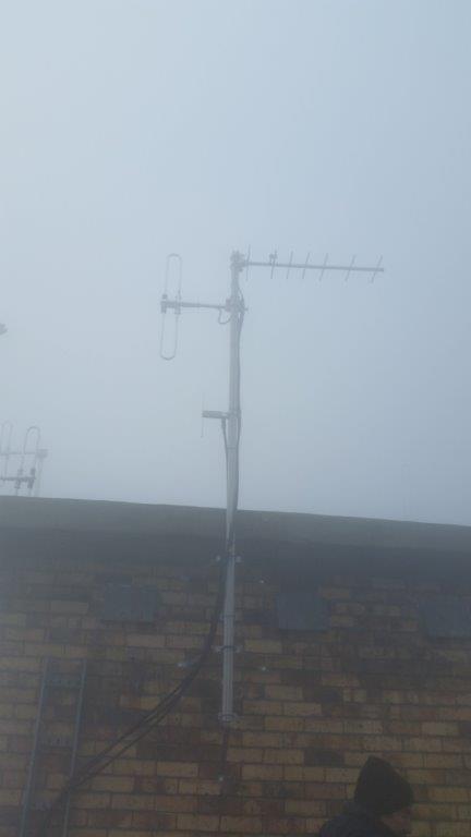
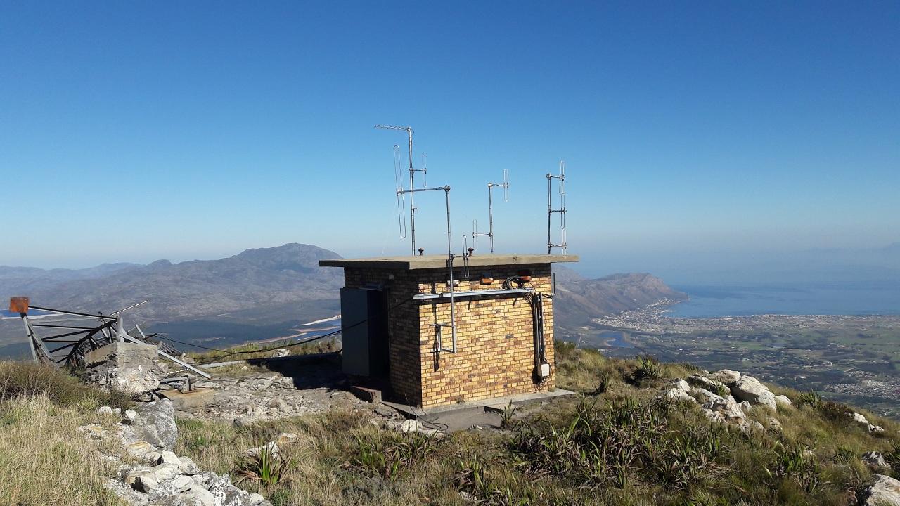
Antennas after install
We left the site around 16:30.
At Strand ZS1AN and ZS1K left for home. ZS1VDV dropped off ZS1YT at home and the recovered Heliax and antennas at ZS1V.
Got home around 18:45 and the vehicle was off loaded by 19:15.
It was one of those days where you leave home in the dark and get home in the dark.
There is a list of todo items for the site. A future maintenance trip will be required.
For the first time ever in the Western Cape Repeater Working Group history. A contact was made between the Piketberg and George repeaters. The path for this contact, Piketberg -> Haweqau -> Bellville -> Hanskop -> Jonaskop -> Riverdal -> Danabaai -> George (8 hops, 15 radios and repeaters)